
OZJ400/J500
Home / Products / Frequency / Up to 3GHz / OZJ400/J500
- Features
- Options
- Applications
- Any module or pair of modules OZ510 or OZ520
- 10 MHz to 3 GHz (6 GHz optional)
- 0°C to +60°C Operating Temperature Range
- CWDM Wavelengths
- High SFDR
- Dynamic Range as High as 70dB, High CNR
- Inline digital attenuator transmitter and receiver RF gain adjustment (J500)
- AGC (30dB range) in transmitter and reciever to extend dynamic range (J500)
- Automatic Optical Power Control
- Hot Swappable
- Multiple local and remote monitoring and control options
- Uncooled DFB Lasers
- MTTF exceeds 10 years at 50°C
- Lasers Conform to Class 1 Emission Level Per CDRH and IEC-825 (EN 60825) Standards
- Integrated +20 dB Transmitter LNA
- Integrated +40 dB Transmitter Dual LNA
- Extended Low Frequency, 10 kHz
- Extended Operating Temperature Range, -20°C to +60°C
- Integrated WDM
- +5 VDC or +12 VDC Bias-T
- Low phase noise reference clock distribution
- TTL over fiber
- GNSS/GPS with antenna status propagation
- RF Over Fiber Transport
- Teleport RF Signal Distribution
- Antenna Site Diversity
- Phased Array Antenna Systems
- Radar Systems RF Signal Transport
- TVRO
- VSAT
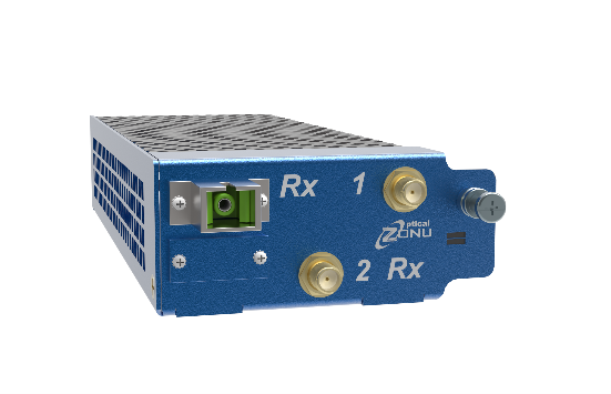
The J400 and J500 are hot swappable J-Chassis plug-in modules that transport 30 – 3000 MHz (or 30 – 6000 MHz) RF signals with high fidelity. Options exist for extending the frequency range to 10 kHz on the lower end. Modules may be configured as single and dual transmitters, single and dual receivers, and transceivers (transmitter + receiver). Transmitters feature linear uncooled isolated DFB laser diodes. Receivers feature high-performance InGaAs photodiodes. The J-Chassis is a 19” 1RU platform (see J-Chassis Overview) that provides 5 (or 10) slots for hot-swappable fiber-optic RF signal transport modules, network management/switches, and power supplies.
Modules are optimized for linear signal transport with high spur free dynamic range (SFDR). The standard RF interface is 50Ω SMA (other impedance/connector options may be available, contact Optical Zonu). A variety of APC optical connector options (SC/APC is standard) are available to maintain low optical reflections throughout the fiber plant.
The J500 modules include an adjustable digital attenuator. In this way, users may manually adjust the RF gain of transmitters and receivers using the preferred Optical Zonu user interface. Both transmitters and receivers have a 30 dB tuning range. J500 transmitters and recievers may also be put into automatic gain control (AGC) mode to extend RF input dynamic range.
RF signals may be transported on dedicated fibers. In subsystems with limited fiber, or where there may be an advantage to transport over a single fiber, coarse wavelength division multiplexing (CWDM) wavelengths are available within the fiber optic transmitters. Single bi-directional links supported by a single fiber are realized by integrating a WDM within the fiber optic transmitters and receivers. More complex traffic architectures may be realized by using external rack-mount CWDM multiplexers.
Options exist for integrating Bias-Ts into transmitters for the purpose of powering elements at the antenna. 5V is the standard center pin Bias-T voltage (12V is also an option, contact Optical Zonu). RF links may also be optimized for transporting low phase noise reference clocks in the frequency range 10 – 200 MHz (J400).
J400/J500 modules may be monitored and controlled in a number of ways. Locally, LEDs on the modules provide health and status indications for each individual transmitter and receiver. There are multiple ways to monitor and control modules remotely when using the JS14 managed switch module within a connected chassis. Administrators may access the RF modules via a serial or SSH connection, a web user interface, and Optical Zonu’s embedded Managed RFoF graphical user interface. The JS14 module also supports SNMP v2 and v3.