
Micro-OTDR Technology
Home / Modules / Small Modules / OZ200
Home » Products » Small Modules » Micro-OTDR Technology
What is SPECIAL about the Micro-OTDR™ SFP Transceiver – μOTDR™ Fast Fiber Fault Finder™
- Standard SFP / SFP+ format fits in any networking equipment
- When link breaks – distance to fault is available
- Features
- Benefits
The configuration is standard: SFP/SFP+ (Small Form-Factor Pluggable). When the fiber is cut, disconnected or broken the distance to the break point is instantly reported.
- Data rates are FE, OC3, GbE, OC48, and 10G.
- Immediate plug-in replacement of an existing SFP/SFP+.
- Automatically generates Link “Birth Certificate”.
- Fast Response Time
• Supports Interactive Mapping Capability
• OpEx Reduction
• Reduced Network Down-Time
Overview:
- Standard SFP (MSA Form Factor) links automatically (like any SFP) with a counterpart at the other end of the optical fiber link.
- Upon detecting a link “break”, or fault, the unit transforms into a Micro-OTDR™.
- For the single fiber version – patented single wavelength duplex CWDM transport.
- High optical power pulses are sent and sensitive circuitry measures all reflections detected.
- Internal processing eliminates false detection, and ensures reliable measurement of more than 10 reflection points (e.g. bad splice, micro crack, dirty connectors, etc.)
- All results are available, via IIC bus of the SFP, to the host Switch.
- Our S11 media converter enables demonstration and retention of the optical fiber link “birth certificate” (the initial measurement of the link distance, and any reflections) and SNMP creates “traps” of any change in the optical fiber link status.
- A special feature called Delta Power Sense (DPS), detects fast optical transients and intrusion attempts.
- When a fault is detected (LOS goes High), the Micro-OTDR™ SFP automatically changes over to Micro-OTDR™ mode. It will return to data transport mode when the fault is resolved (i.e. LOS goes Low).
- Features
- Options
- Applications
- 30 MHz to 3, 4, 6 GHz
- Enable ultra high dynamic range (60dB)
- Adjustable Transmitter and Receiver RF Gain (30 dB or 60dB range each)
- Signal strength detectors
- Optional AGC in Transmitter and Receiver
- Digitally controlled via a microcontroller
- Interface via USB, I2C, or UART
- 1310 nm, 1550 nm, CWDM Wavelengths
- High SFDR
- 1310 nm, 1550 nm, CWDM Wavelengths
- +7V Supply Voltage
- -40°C to +70°C Operating Case Temperature Range
- Automatic Optical Power Control
- Local LED Alarm Indicators
- Uncooled Isolated DFB Lasers
- Lasers Conform to Class 1 Emission Level Per CDRH and IEC-825 (EN 60825) Standards
- Up to 4 UNITS (Tx and/or Rx) can be mounted in a single J3U slot LINK.
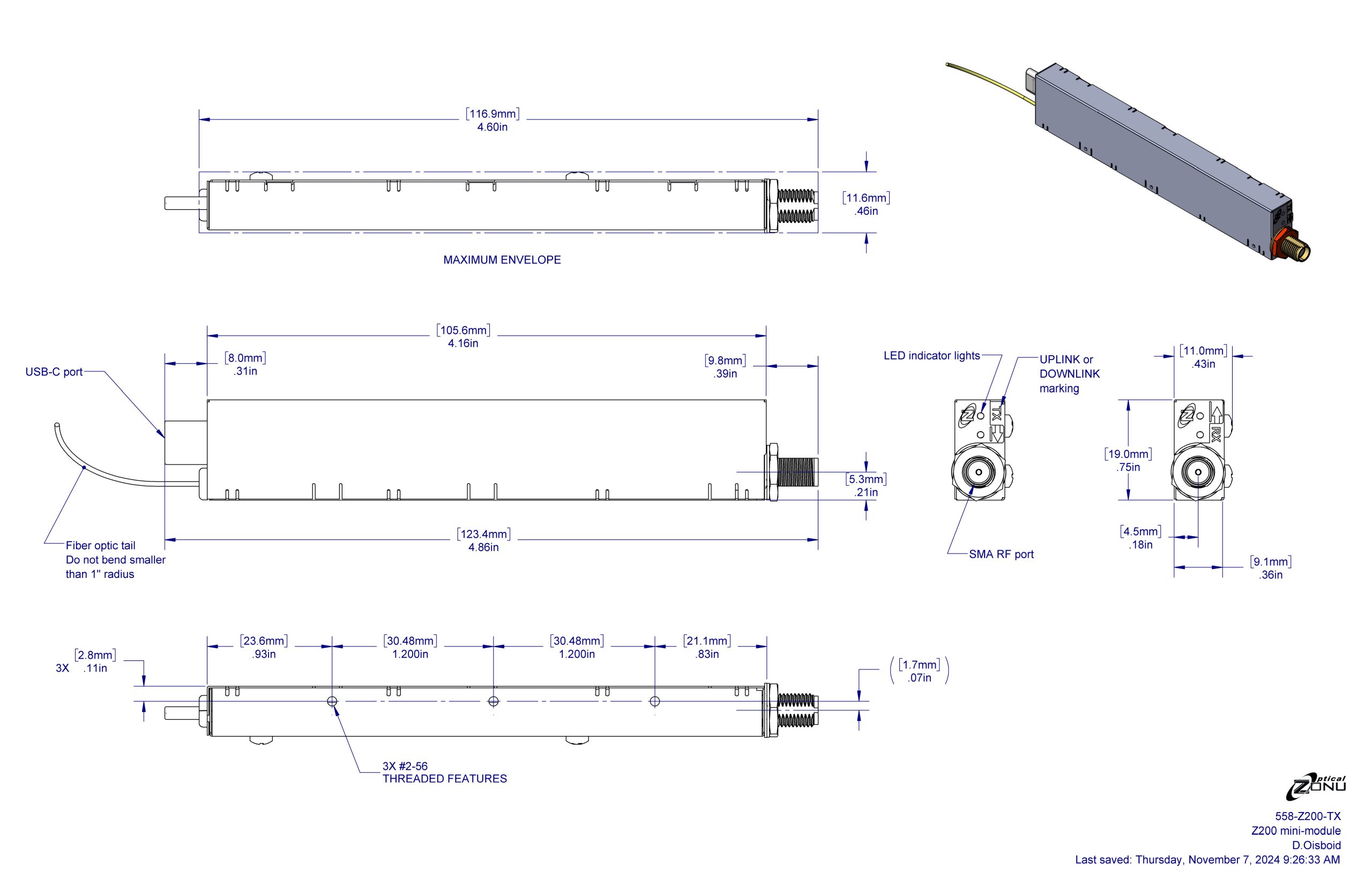
- Small Size, 0.7″x4.2″x0.35″ / 19mm x 106mm x 9mm
- Weighs 32 Grams
- Integrated +35 dB High Gain Transmitter LNA
- Up to 60 dB RF Gain Tuning Range in Transmitter
- Access to RF RMS power measurement
- AGC
- Extended 1 MHz Low Frequency Available
- Low Phase Noise Reference Clock Distribution (10 – 200 MHz)
- Multimode Fiber Capability
- Package 4 in a single Blade (slot) of J3U or in a J3U Single card enclosure.
- MORE – contact Optical Zonu
- RF Over Fiber Transport
- High Dynamic Range Links (256 QAM)
- Teleport RF Signal Distribution
- High Density Deployments
- Antenna Site Diversity
- Phased Array Antenna Systems
- Radar Systems RF Signal Transport
- Avionics
- 4G LTE 5G CBRS
- Satcom
- Cellular Communications
Product Description
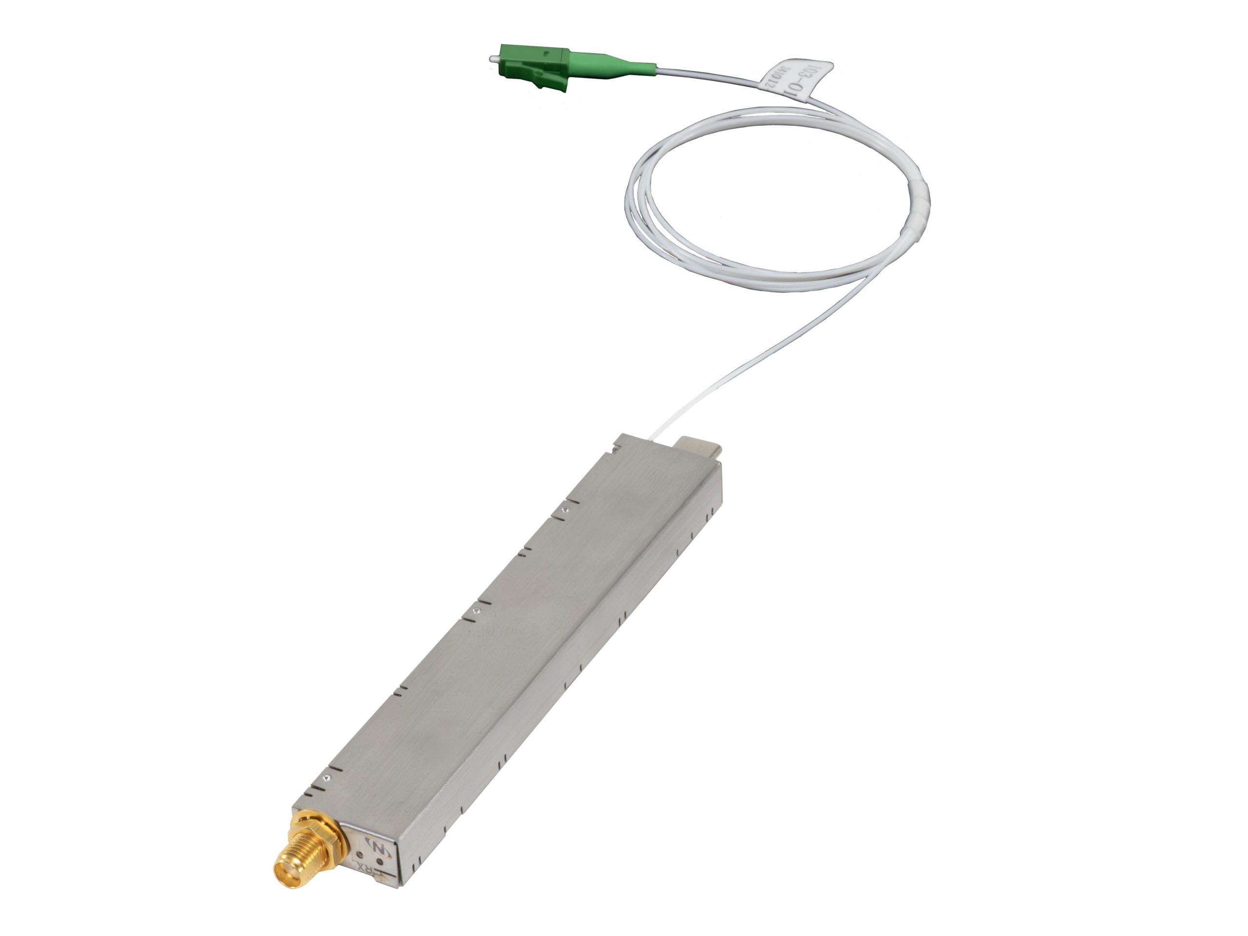
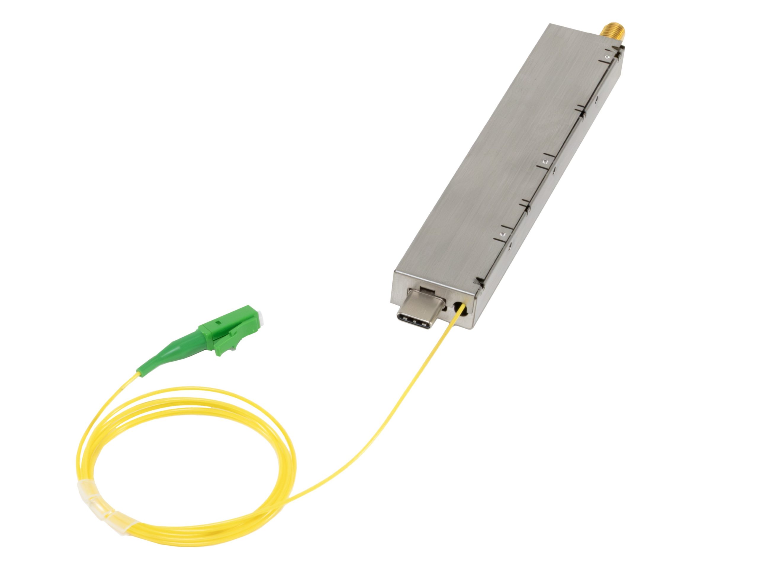
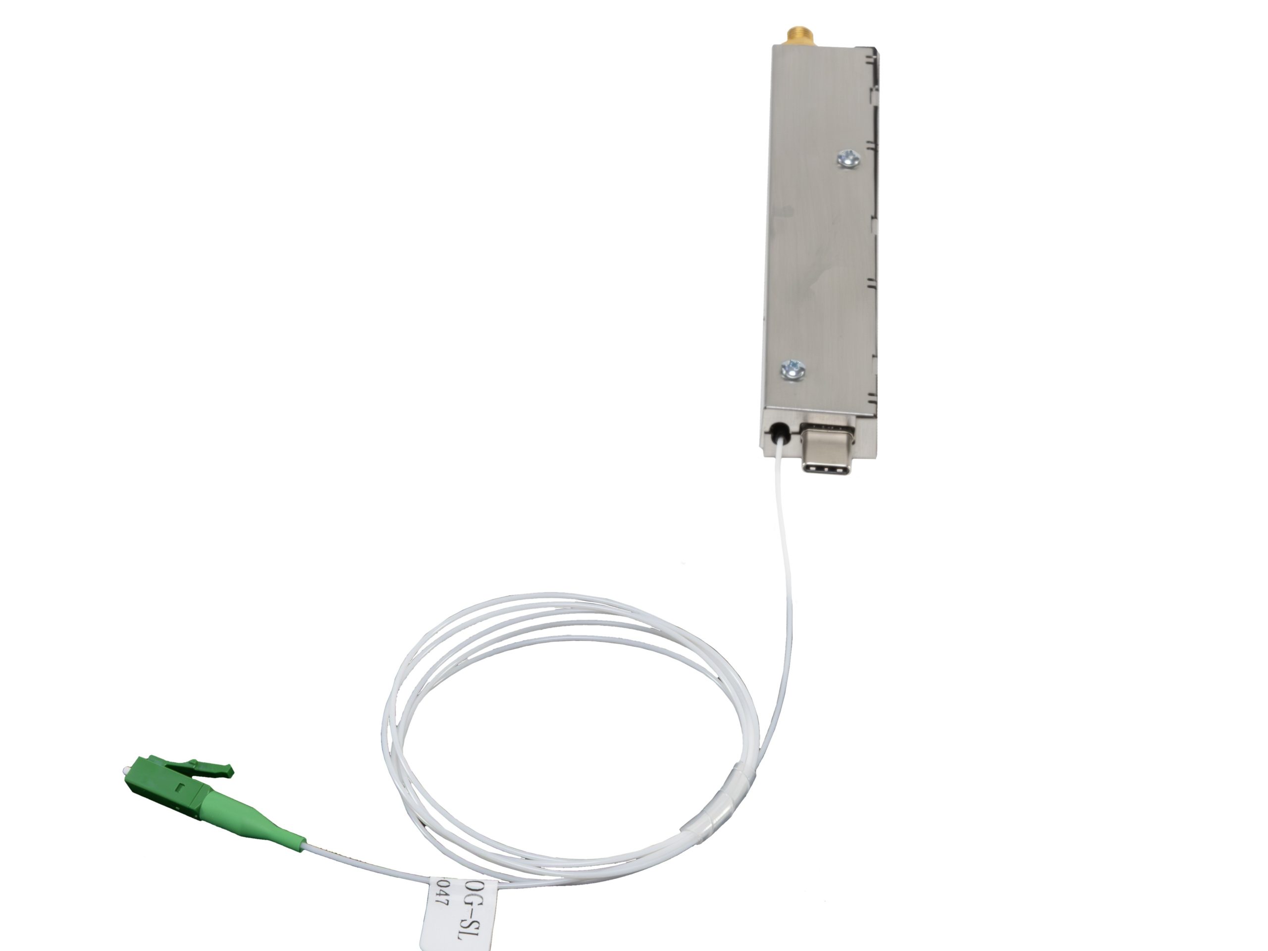
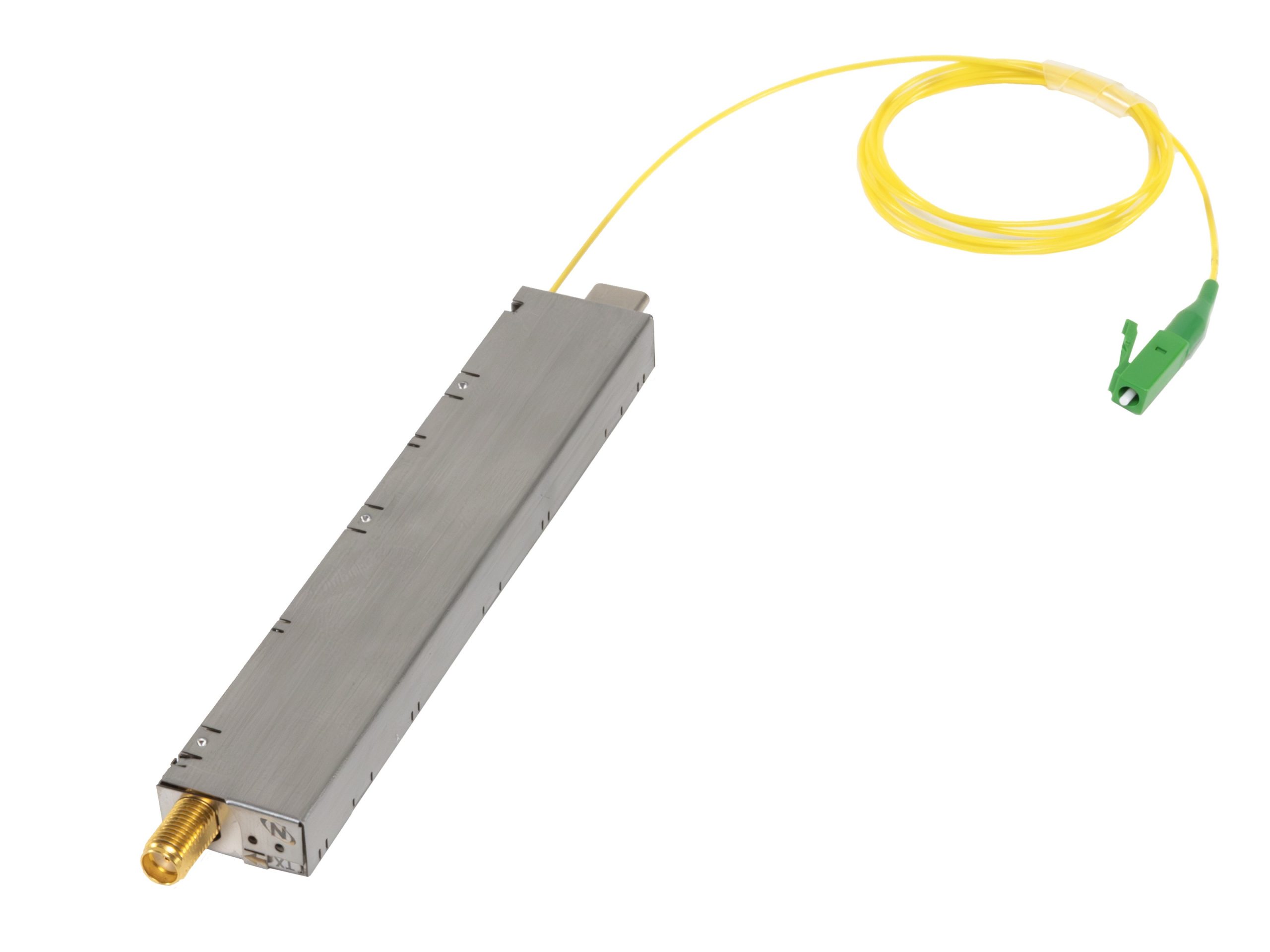
The OZ20x OEM fiber optic transmitter and receiver modules are broadband RF over Fiber standalone enclosed board level assemblies that are well-suited for low size/ weight/power (such as drone and UAV) applications. The OZ20x was specifically designed for very wide dynamic range (>60dB) and supports RF transport in situations where transport distance or flexibility of cabling may prohibit the use of coaxial cable.
Inline digital attenuators enable both transmitter and receiver RF gain control. Both Manual Gain adjust (MGC) and closed loop Automatic Gain Control (AGC) are supported in the fiber transmitters and receivers. MGC and AGC modes enable optimization of spurious free dynamic range (SFDR), noise figure, linearity (P1dB and IIP3), and RF gain over a wide variety of optical loss budgets and RF signal levels. Built-in RF shielding supports low EMI/RF interference.
Transmitters feature linear uncooled isolated DFB laser diodes. CWDM wavelengths are available. Average Automatic Power Control (AAPC) provides closed loop control of the transmitter optical output power over the full operating temperature range. Receivers feature high performance InGaAs photodiodes. The standard transport RF frequency band is 30 – 3,000 MHz. Options exist for extending the frequency range to 1 MHz on the lower end and 6 GHz on the higher end. The RF interface is 50Ω SMA. SC/APC optical fiber pigtails are standard to maintain low optical reflections throughout the fiber plant. Contact Optical Zonu for other options. Standard transport is over 9/125 μm single mode fiber, however Multimode fiber transport is also an option (contact Optical Zonu for details).
The OZ20x module power and digital interface is provided on an industry standard USB-C connector. Monitoring and control are via a USB, I2C, or UART physical interface. LEDs provide local status of fiber transmitter and receiver. OZ20x modules are powered from 6.5 VDC.
OZ20x transmitter and receiver modules may be integrated into 19” rack mounted architectures to provide very dense RF over fiber transport. Up to 64 transmitter and/or receiver modules can be fit into a 19” 3RU J3U Chassis by utilizing the J3U plug-in modules. (see the J3U Quad Transport Datasheet). RF links may also be optimized for transporting low phase noise reference clocks in the frequency range 10 – 200 MHz.