Iridium Indoor Extender
Home / Modules / Small Modules / OZ200
Home » Products » Fixed (19″ Rack) » Iridium Indoor Extender
- Features
- Options
- Applications
- System is Transparent to any Approved Iridium Equipment
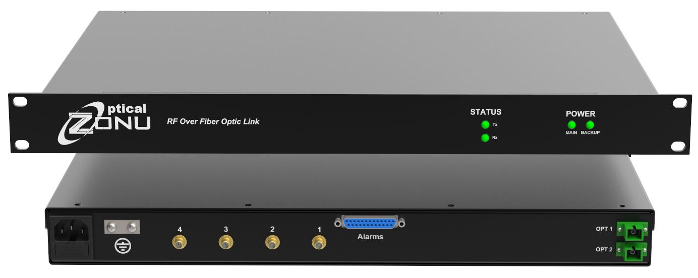
- 19” 1RU Chassis Supports Connection of up to Four Phone/Cradles OR Re-Rad antenna(s)
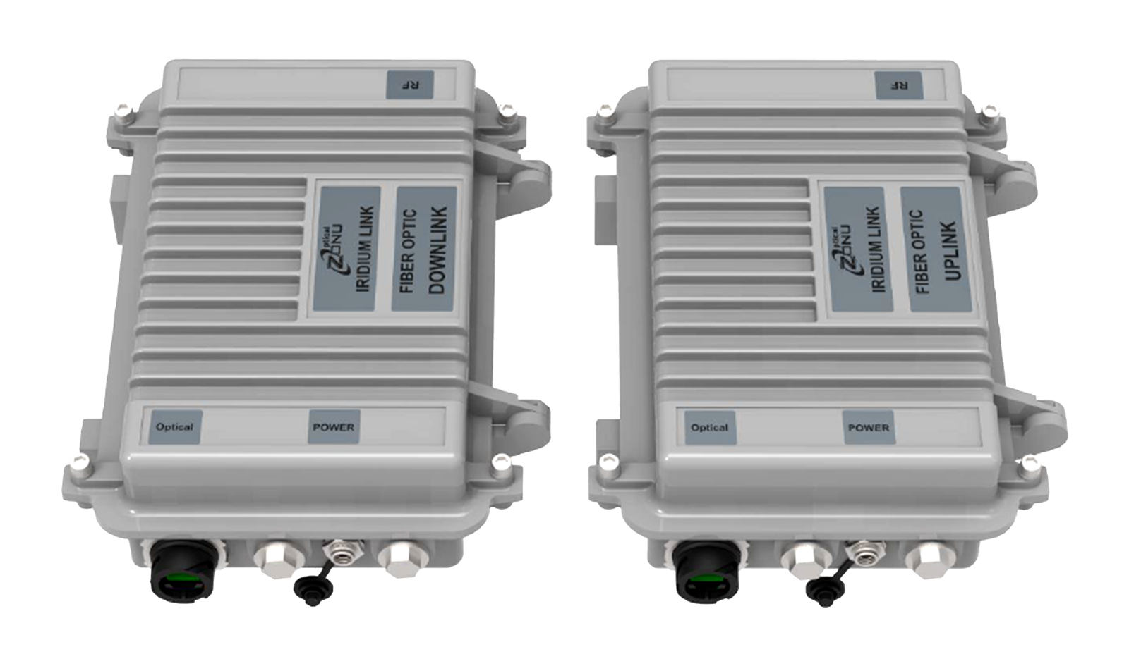
- Environmentally Hardened IP-67 Outdoor Enclosures House Active RF and Fiberoptic Components
- Support for Direct Connection of Phone Docking Stations to Indoor Unit Over Copper
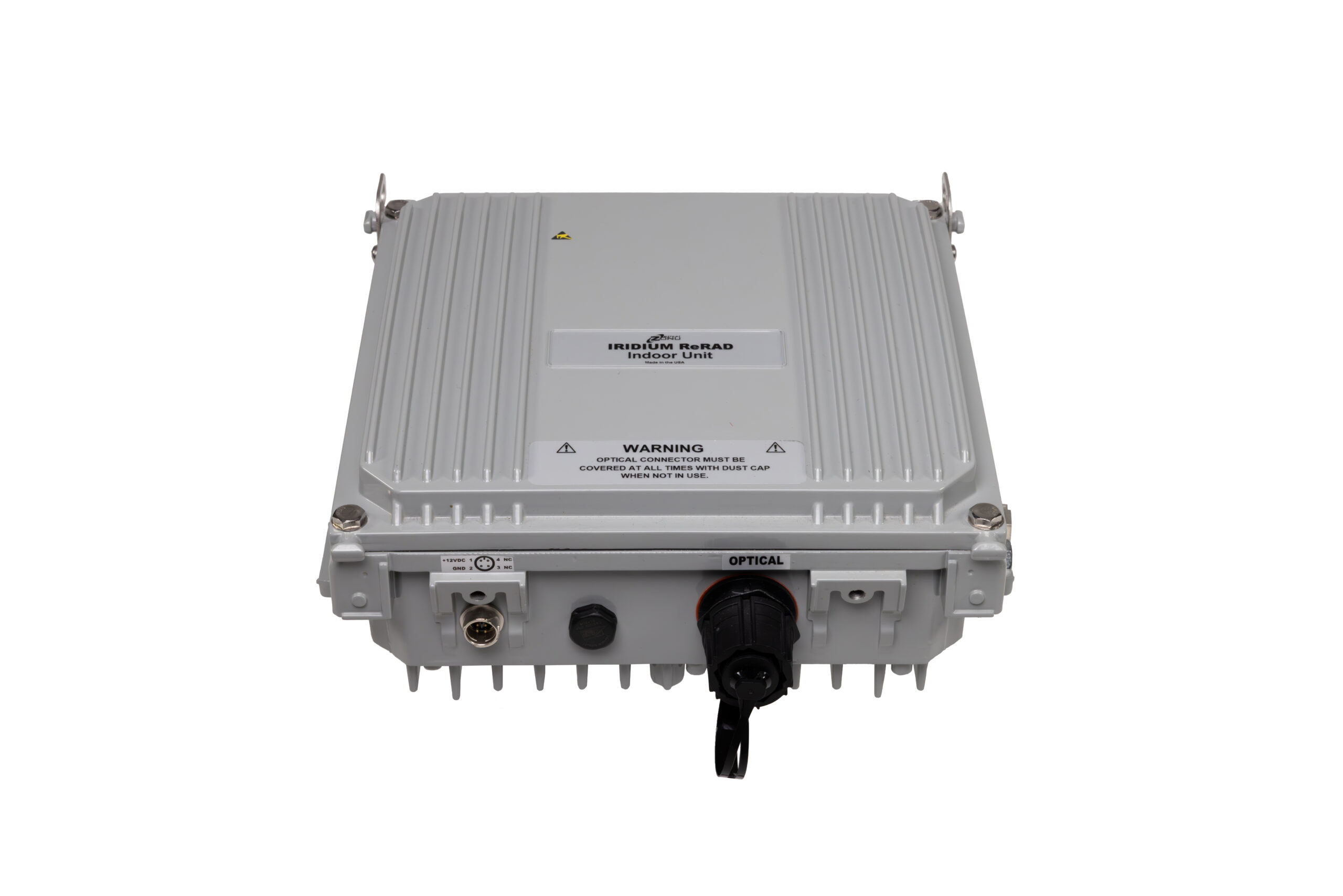
- Ceiling Mount Indoor Termination Supports Re-Radiating Indoor Antennas
- Support for Voice and Data Modems
- Fiber Cabling Supports Location of Indoor Equipment up to 1 km Away From Outdoor Line-of-Sight Antennas
- Local LED and Dry Contact Alarms
- Dual Universal AC Power Supply
- Systems Available to Support Globalstar, Inmarsat, and Thuraya Requirements
- Lasers Conform to Class 1 Emission Level Per CDRH and IEC-825 (EN 60825) Standards
- Receive Only Satellite Paging + GPS Transport (contact Optical Zonu)
- Multimode Fiber Compatibility (not available for systems with two indoor terminations)
- Large Buildings
- Underground Facilities, Mines, Tunnels
- Maritime
- Oil & Gas Platforms
- Secure Government Facilities
- Disaster Recovery
Product Description
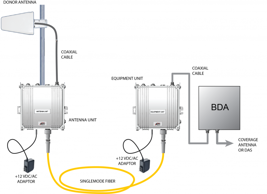
Optical Zonu’s Iridium over fiber solution is designed for applications requiring satellite communications where a clear line-of-sight to the Iridium satellite constellation is not available. Outdoor antennas are connected to indoor or underground satellite phone locations via fiber. Indoor equipment may be located up to 1 km away from Iridium line-of-sight antennas.
The Optical Zonu Iridium fiber transport subsystems are transparent to any Iridium certified communication equipment. If an Iridium phone/cradle connects directly to outdoor antennas over coaxial cable, they will connect transparently using the Optical Zonu fiber distribution system. As with any Iridium certified equipment, the Optical Zonu fiber transport subsystem also supports both voice and data services. GNSS/GPS may also be supported on the downlink (contact Optical Zonu).
The Iridium over-the-air link protocol is TDD. Uplink and downlink carrier frequencies are the same, hence communication is achieved by dividing the single frequency channel into timeslots. The Optical Zonu architecture maintains sufficient Eb/N0 (i.e., bit error rate) and the uplink and (more critically) on the downlink by physically separating the uplink and downlink antenna/paths. This provides the necessary isolation between uplink and downlink. With the Optical Zonu implementation of separated antennas, the uplink transmitted power may be fully 10W without interfering with the downlink.
Fiber transmitters feature linear uncooled isolated DFB laser diodes. Receivers feature high performance InGaAs photodiodes. The standard RF interface to the indoor 19” 1RU chassis is 50Ω SMA. The 19” chassis is powered by dual AC or –48 VDC (optional) power supplies. Outdoor equipment as well as the indoor ceiling mount re-radiating termination are powered from +12 VDC.
Locally, status LEDs are present on both the front and the back of the 19” 1RU indoor chassis. Alarm and monitor functions are also available via dry relay contacts accessed by means of a DB25 connector on the back of the chassis.
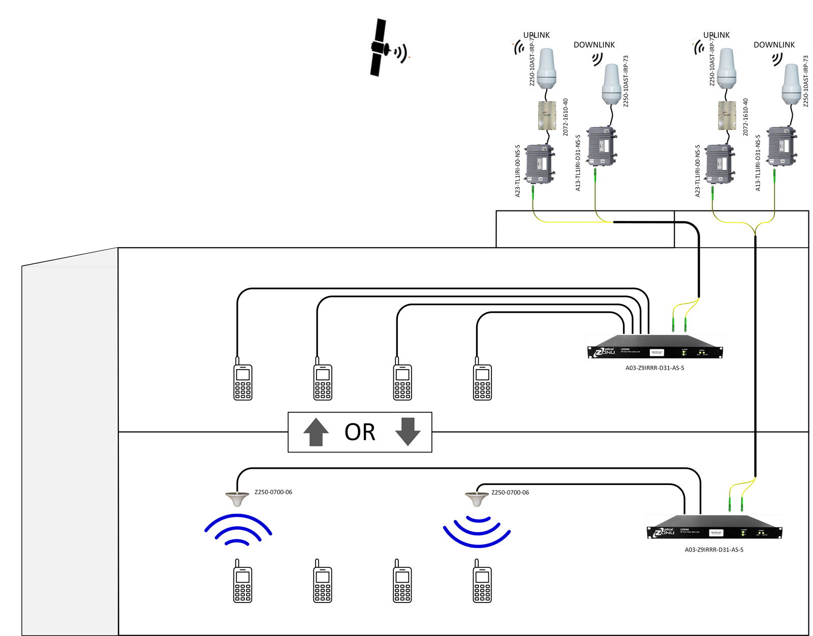
Iridium in Building

Schematic connection for Iridium distribution