
RF over Fiber for GPS/GNSS Synchronization: Reliable Timing Distribution Over Fiber
RF over Fiber for GPS/GNSS Synchronization: Reliable Timing Distribution Over Fiber
Modern communications, data center, defense, SATCOM, wireless, transportation, and critical infrastructure systems often depend on extremely accurate timing and synchronization.
GPS and other Global Navigation Satellite Systems (GNSS) provide highly stable reference signals that allow equipment in different locations to maintain a common timing source. But delivering those signals from an outdoor antenna with clear sky visibility to timing equipment located hundreds or thousands of feet away can present a significant engineering challenge.
Traditional coaxial cable introduces increasing signal loss as distance increases. Routing requirements, electromagnetic interference, grounding concerns, and the need to distribute a single antenna signal to multiple locations can further complicate system design.
RF over Fiber (RFoF) provides an alternative.
By converting GPS/GNSS RF signals into optical signals, transporting them over fiber, and converting them back to RF at the destination, RF fiber optic links can extend precision timing signals over long distances while providing flexible, scalable distribution architectures.
Why GPS and GNSS Are Used for Synchronization
Although GPS is best known as a positioning technology, GPS and other GNSS constellations also provide highly accurate timing references.
Timing receivers can use these satellite signals to discipline local clocks and synchronize equipment across distributed systems.
Applications include:
- Cellular base stations and wireless networks
- Data centers and server farms
- SATCOM ground systems
- Defense communications
- Radar systems
- Broadcast networks
- Utility and power infrastructure
- Transportation systems
- Public safety networks
- Test and measurement facilities
In these applications, GPS/GNSS is not simply providing location information. It becomes part of the system’s timing infrastructure.
The GPS/GNSS Signal Distribution Challenge
GPS/GNSS antennas typically require an outdoor location with adequate sky visibility.
The equipment that uses the timing reference, however, may be located somewhere entirely different: inside a building, underground, below deck, in an equipment shelter, within a secure facility, or across a large campus.
Connecting those locations with coaxial cable becomes increasingly difficult as distance increases.
GNSS signals are located around the 1.6 GHz region, where coaxial attenuation can become significant. Long coaxial runs can reduce signal-to-noise ratio and may require larger cable, amplifiers, or other compensation techniques.
The challenge becomes even greater when one antenna signal must be delivered to many receivers.
RF over optical fiber changes the physical limitations of that connection.
How GPS/GNSS Over Fiber Works
A GPS/GNSS over Fiber system uses the same fundamental architecture as other analog RF over Fiber systems.
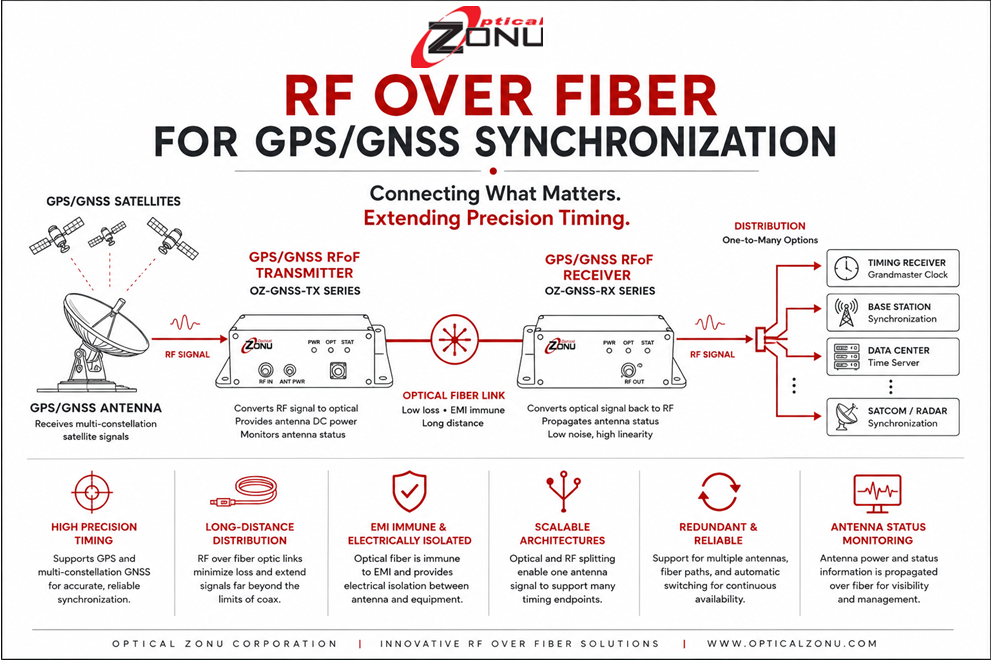
The signal received by the GPS/GNSS antenna enters an RFoF transmitter. The transmitter converts the RF signal into an optical signal, which travels over fiber optic cable.
At the destination, an optical receiver converts the signal back to RF and delivers it to the GPS/GNSS receiver, timing server, base station, radio, or other synchronization equipment.
A simplified architecture looks like this:
GPS/GNSS Satellites
↓
GPS/GNSS Antenna
↓
RF over Fiber Transmitter
↓
Optical Fiber Link
↓
RF over Fiber Receiver
↓
Timing Receiver / Grandmaster / Network Equipment
The RF interfaces at each end remain familiar to the timing equipment. The fiber optic link provides the transport path between them.
In this sense, GPS/GNSS RF over fiber optic links can function as transparent optical extensions between antennas and timing receivers.
Why Use RF over Fiber Instead of Coax?
Long-Distance Signal Transport
One of the primary reasons for using RF over Fiber for GPS/GNSS synchronization is distance.
Fiber introduces substantially less transmission loss over long distances than RF coaxial cable, allowing the antenna and timing equipment to be separated by distances that may otherwise be impractical.
This gives system designers much greater freedom when selecting antenna and equipment locations.
EMI Immunity
Optical fiber does not conduct RF or electrical energy and is inherently immune to electromagnetic interference.
That characteristic can be especially valuable in environments containing high-power RF equipment, radar, wireless infrastructure, industrial machinery, or other potential sources of interference.
Electrical Isolation
Because the transport medium is dielectric rather than conductive, fiber provides electrical isolation between the antenna location and downstream equipment.
This can help simplify system architecture in installations where grounding and electrical separation are important considerations.
Smaller and Lighter Cabling
Fiber is significantly smaller and lighter than many long-distance RF coaxial cables.
This can simplify routing through buildings, equipment facilities, mobile platforms, aircraft, ships, tunnels, and other environments where cable pathways or weight may be constrained.
GPS/GNSS Timing Distribution to Multiple Locations
Many synchronization systems require more than a simple point-to-point connection.
A single GPS/GNSS antenna may need to provide timing signals to multiple equipment rooms, racks, base stations, timing servers, or other endpoints.
Optical distribution provides an efficient way to scale these architectures.
RF over Fiber systems can incorporate optical splitting, RF splitting at the receiver, or combinations of both to distribute GPS/GNSS signals to multiple destinations.
This allows engineers to create architectures such as:
One Antenna → Multiple Timing Receivers
or
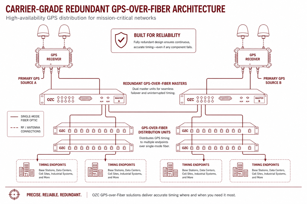
Redundant Antennas → Redundant Fiber Paths → Multiple Equipment Locations
As networks grow, this scalability becomes increasingly important.
Redundancy and Timing-System Resilience
Timing can be mission-critical.
A failure in the GPS/GNSS distribution path can affect equipment throughout a network, making redundancy an important design consideration.
Advanced GPS/GNSS over Fiber architectures can incorporate:
- Multiple rooftop antennas
- Redundant RF over Fiber transmitters
- Alternate fiber routes
- Redundant optical receivers
- Automatic RF switching
- Redundant power supplies
- Alarm and monitoring systems
This allows engineers to design timing infrastructures that can continue operating even when individual components or signal paths fail.
For carrier networks, data centers, defense systems, and other critical infrastructure, eliminating single points of failure can be as important as extending the signal itself.
Antenna Status Monitoring
One challenge with distributed GPS/GNSS systems is knowing whether the remote antenna and its connection are operating properly.
When the antenna may be hundreds or thousands of feet from the timing equipment, simple physical inspection is not practical.
Modern RFoF timing systems can propagate antenna-status information through the optical link, allowing equipment at the receiving location to monitor conditions at the remote antenna.
This gives system operators greater visibility into the complete signal path and can simplify troubleshooting and maintenance.
Supporting Multiple GNSS Constellations
Modern timing architectures increasingly use more than GPS alone.
Depending on system requirements and geographic location, timing receivers may use signals from multiple GNSS constellations, including:
- GPS
- GLONASS
- Galileo
- BeiDou
- NavIC
- QZSS
A broadband RF fiber optic link can transport multiple GNSS frequencies transparently, allowing the timing receiver to process the satellite signals it is designed to support.
This provides greater flexibility than designing the optical transport architecture around a single satellite constellation.
Propagation Delay and Precision Timing
Any transmission medium introduces propagation delay.
For precision synchronization applications, that delay needs to be understood and, where necessary, compensated.
Optical fiber introduces a predictable delay based primarily on fiber length. The RF over Fiber transmitter and receiver add comparatively little additional delay.
Because fiber delay is deterministic, timing receivers and synchronization systems can compensate for known link delay when very high timing accuracy is required.
This is an important distinction: RF over Fiber does not eliminate propagation delay. Instead, it provides a stable and measurable transport path whose delay can be incorporated into the timing-system design.
Signal Integrity in GPS/GNSS RFoF Links
GPS/GNSS satellite signals arrive at the antenna at very low signal levels.
Maintaining adequate signal-to-noise ratio through the distribution system is therefore important.
Engineers evaluating RF over Fiber optic links for timing applications should consider:
- Frequency range
- Noise figure
- RF gain
- Optical loss
- Dynamic range
- Fiber distance
- Number of optical splits
- Number of RF outputs
- Antenna power requirements
- Redundancy requirements
- Monitoring capabilities
The complete signal path should be evaluated rather than considering the fiber link independently.
GPS/GNSS Synchronization Applications
RF over Fiber timing distribution can support a broad range of systems.
Wireless Networks
Cellular networks require accurate synchronization between base stations and other network elements. GPS/GNSS reference signals can be delivered over fiber to base station equipment or to grandmaster timing servers that distribute timing throughout the network.
Data Centers
Large data centers may require GPS/GNSS timing signals at multiple equipment rooms or rack locations.
Fiber allows rooftop antennas to serve timing equipment located deep inside large facilities while also supporting redundant architectures.
SATCOM Systems
Satellite communication gateways and ground stations may rely on common timing references across geographically or physically separated equipment.
GPS/GNSS over Fiber provides a practical method of distributing those references throughout the facility.
Defense and Aerospace
Military bases, aircraft facilities, radar installations, command centers, test ranges, and other defense environments often require reliable timing distribution while maintaining electrical isolation and immunity to EMI.
Critical Infrastructure
Utilities, transportation systems, public safety networks, financial systems, broadcast facilities, and other critical infrastructure can also depend on precise synchronization.
In these environments, timing distribution must often combine accuracy with reliability, redundancy, monitoring, and long-distance signal transport.
Selecting an RF over Fiber System for GPS/GNSS Synchronization
When selecting an RF over Fiber solution for GPS/GNSS timing distribution, engineers should evaluate both RF performance and the complete system architecture.
Important considerations include:
- Supported GPS/GNSS frequency bands
- Number of satellite constellations required
- Distance between antenna and timing equipment
- Fiber type and available infrastructure
- Optical loss budget
- Required number of endpoints
- RF and optical splitting requirements
- Antenna DC power requirements
- Gain and noise performance
- Redundancy requirements
- Alarm and monitoring requirements
- Environmental conditions
- Future expansion
A point-to-point installation may require only a simple transmitter and receiver.
A carrier network or data center, however, may require multiple antennas, redundant optical paths, optical splitters, automatic switching, multiple receivers, and centralized monitoring.
Choosing the architecture rather than simply choosing individual components is therefore an important part of GPS/GNSS timing-system design.
Optical Zonu GPS/GNSS Over Fiber Solutions
Optical Zonu provides GPS/GNSS RF over Fiber solutions ranging from compact point-to-point links to large, redundant timing-distribution systems.
Available architectures support GPS and other international GNSS frequencies, long-distance fiber transport, optical and RF signal splitting, redundant antenna and fiber paths, antenna-status propagation, and high-density distribution to multiple endpoints.
These systems allow engineers to build RF fiber optic links around the requirements of the timing infrastructure rather than allowing coaxial cable distance limitations to dictate equipment placement.
For complex carrier, data center, defense, wireless, SATCOM, or critical infrastructure applications, the architecture can be configured around required distance, redundancy, endpoint count, optical routing, monitoring, and reliability requirements.
Extending Precision Timing with Fiber
As networks become larger, more distributed, and increasingly dependent on accurate synchronization, transporting GPS/GNSS reference signals reliably becomes part of the system architecture itself.
RF over Fiber allows engineers to separate antennas from timing equipment, distribute signals across long distances, reduce the limitations of coaxial cable, provide electrical isolation, and create scalable redundant timing networks.
Whether the requirement is a single GPS antenna connected to a remote receiver or a highly redundant GNSS distribution network serving many endpoints, RF over Fiber (RFoF) provides a flexible optical transport architecture for extending precision timing wherever it is needed.
Related Links
RF over Fiber vs. Coaxial Cable
RF over Fiber in Aerospace & Defense Applications