Wide (Ultra-wide) Dynamic Range
Home » Solutions » Special Functions » Wide (Ultra-wide) Dynamic Range
- Features
- Options
- Applications
- Up to 4 Transmit and/or Receive Signals per Plug-in Module
- 30 MHz to 3, 4, 6 GHz
Adjustable Tx and Rx RF Gain (30 dB range each) - Demonstrated dynamic range > 60dB
- Optional AGC in Transmitter and Receiver
- -20°C to +55°C Operating Temperature Range
- 1310 nm, 1550 nm, CWDM Wavelengths
- High SFDR
- Automatic Optical Power Control
- Hot Swappable
- Multiple Local and Remote
- Monitoring and Control Options
- Uncooled DFB Lasers
- Lasers Conform to Class 1 Emission Level Per CDRH and IEC-825 (EN60825) Standards
- Integrated +35 dB High Gain Transmitter LNA
- Up to 60 dB RF Gain Tuning Range in Transmitter
- Extended Operating Temperature Range, -20°C to +60°C
- Integrated WDM
- RF Over Fiber Transport
- Teleport RF Signal Distribution
- RF and Optical Redundancy
- Antenna Site Diversity
- Phased Array Antenna Systems
- Radar Systems RF Signal Transport
- TVRO
- VSAT
Description
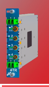
The J3U platform (see J3U Platform Overview) is a 19” 3RU chassis that accommodates (among other things) 16 pluggable, hot swappable fiber optic RF signal transport modules. Each RFoF J3U Quad plug-in module can accommodate up to four fiber transmitter and/or fiber receivers (in any combination). A single 3RU chassis can house up to 64 transmitter and/ or receiver RFoF subassemblies. The individual transmitter and receiver subassemblies are not pluggable.
Inline digital attenuators (0.5 dB steps) enable both transmitter and receiver RF gain control. Both manual gain adjust (MGC) and closed loop automatic gain control (AGC) are supported in the fiber transmitters and receivers. MGC and AGC modes enable optimization of spurious free dynamic range (SFDR), noise figure, linearity (P1dB and IIP3), and RF gain over a wide variety of optical loss budgets and RF signal levels.
Transmitters feature linear uncooled isolated DFB laser diodes. Receivers feature high performance InGaAs photodiodes. The standard transport RF frequency band is 30 – 3,000 MHz. Options exist for extending the frequency range to 1 MHz on the lower end and 6 GHz on the higher end.
The RF interface is 50Ω SMA. LC/APC optical connectors are standard on Quad plug-in modules to maintain low optical reflections throughout the fiber plant. Single bi-directional links transported on a single fiber are realized by integrating a WDM within the fiber optic plug-in modules. More complex traffic architectures may be realized by using external rack mount CWDM Multiplexers.
Built-in RF shielding facilitates low EMI/EMC/RF interference. RF signal transport modules within the J3U platform may be monitored and controled in a number of ways. Locally, LEDs on the modules provide health and status indications for each individual transmitter and receiver. There are multiple ways to monitor and control modules remotely when using the JS14 managed switch module within a connected chassis. Administrators may access the RF modules via an SSH command line interface, tabular Web UI, Managed RFoF graphical user interface (GUI), and SNMP v2 and v3 (see JS14 Managed Switch datasheet).
- Features
- Options
- Applications
- Individual Modules Tx and Rx OZ200
- 80dB dynamic range of the input signal
- J3U slot can be configured with up tp 4 OZ200 units
- J3U slot can be set to 4 Transmit and/or Receive Signals per Plug-in Module
- 30 MHz to 3, 4, 6 GHz
- Adjustable Transmitter and Receiver RF Gain (30 dB range each)
- Optional AGC in Transmitter and Receiver
- -20°C to +55°C Operating Temperature Range
- CWDM Wavelengths
- High SFDR
- Automatic Optical Power Control
- Hot Swappable
- Multiple Local and Remote Monitoring and Control Options
- Uncooled DFB Lasers
- Lasers Conform to Class 1 Emission Level Per CDRH and IEC-825 (EN60825) Standards
- Integrated +35 dB High Gain Transmitter LNA
- Up to 60 dB RF Gain Tuning Range in Transmitter
- Extended Operating Temperature Range, -20°C to +60°C
- Integrated WDM
- RF Over Fiber Transport
- Teleport RF Signal Distribution
- RF and Optical Redundancy
- Antenna Site Diversity
- Phased Array Antenna Systems
- Radar Systems RF Signal Transport
- TVRO
- VSAT
OZ200 is a standalone module that is feature rich and can be set in multiple configuration at the factory and controlled by the customer via USB back connector.
The J3U platform (see J3U Platform Overview) is a 19” 3RU chassis that accommodates (among other things) 16 pluggable, hot swappable fiber optic RF signal transport modules. Each RFoF J3U Quad plug-in module can accommodate up to four fiber transmitter and/or fiber receivers (in any combination). A single 3RU chassis can house up to 64 transmitter and/ or receiver RFoF subassemblies. The individual transmitter and receiver subassemblies are not pluggable.
Inline digital attenuators (0.5 dB steps) enable both transmitter and receiver RF gain control. Both manual gain adjust (MGC) and closed loop automatic gain control (AGC) are supported in the fiber transmitters and receivers. MGC and AGC modes enable optimization of spurious free dynamic range (SFDR), noise figure, linearity (P1dB and IIP3), and RF gain over a wide variety of optical loss budgets and RF signal levels.
Transmitters feature linear uncooled isolated DFB laser diodes. Receivers feature high performance InGaAs photodiodes. The standard transport RF frequency band is 30 – 3,000 MHz. Options exist for extending the frequency range to 1 MHz on the lower end and 6 GHz on the higher end.
The RF interface is 50Ω SMA. LC/APC optical connectors are standard on Quad plug-in modules to maintain low optical reflections throughout the fiber plant. Single bi-directional links transported on a single fiber are realized by integrating a WDM within the fiber optic plug-in modules. More complex traffic architectures may be realized by using external rack mount CWDM Multiplexers.
Built-in RF shielding facilitates low EMI/EMC/RF interference. RF signal transport modules within the J3U platform may be monitored and controled in a number of ways. Locally, LEDs on the modules provide health and status indications for each individual transmitter and receiver. There are multiple ways to monitor and control modules remotely when using the JS14 managed switch module within a connected chassis. Administrators may access the RF modules via an SSH command line interface, tabular Web UI, Managed RFoF graphical user interface (GUI), and SNMP v2 and v3 (see JS14 Managed Switch datasheet).