
Timing / Distribution (GNSS) - Links (indoor / outdoor)
Home » Solutions » Timing / Distribution (GNSS) » Links (indoor / outdoor)

What is GNSS / GPS over Fiber and how do they differ?
Optical fiber provides a cost-effective solution for long coaxial cable runs in GNSS / GPS over Fiber systems. The Optical Zonu GNSS / GPS over Fiber for Network Sync System allows signals to be carried from an antenna to a GNSS / GPS receiver with minimal signal degradation over a non-conducting dielectric glass media. This system provides a completely transparent cross-site connection between an antenna and receiver. As is the case in many types of in-building environments, networks require accurate clock synchronization. By utilizing broadband RF linear (analog) over Fiber Optics (RFoF) Technology, Optical Zonu GNSS / GPS over Fiber Optics Links provide easy to operate, low cost and reliable solutions that enable GNSS / GPS signal distribution using fiber optic cable.
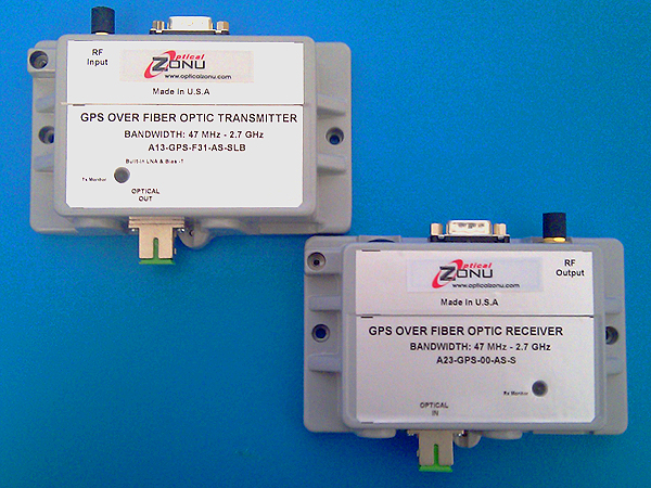
The broad bandwidth (20 MHz to 3.0 GHz) of the RFoF transceivers used in our GNSS / GPS over Fiber Optics Link allows transmission of the two main signals in the GPS band, L1 and L2, at 1575.42 MHz and 1227.6 MHz respectively. This GNSS / GPS over Fiber Link is designed to offer a low noise figure by integrating a built-in LNA with Lasers featuring low Relative intensity Noise (RIN) and low loss broadband matching, in order to optimize the Link performance. Optical Zonu’s GNSS / GPS RFoF Link consists of stand-alone analog (linear) transmitter and receiver units. Each module is housed in a compact (3 x 5 x 1.5 inches) metal ruggedized box which allow convenient installation in small spaces. Both units are powered via a DB-9 plug using +12 Volts DC (optional power supplies are available upon request).
Optical Zonu’s GPS RFoF Link is an ideal solution for providing GNSS / GPS timing and reference signals over fiber optic cable. It acts as a low loss extender between the GNSS / GPS antenna and GNSS / GPS receiver in places where GNSS / GPS signals are otherwise unavailable, or where running long coaxial cable lines is impractical.
GPS POINT-TO-POINT LINK
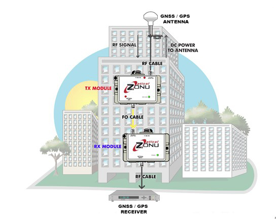
This segment addresses the most basic of all GNSS / GPS applications, which requires point-to-point links over fiber optic cable. A link consists of transmitter and receiver modules. Both modules are packaged in a semi-ruggedized, dust-tight, cast metal housing. The transmitter has a built-in LNA with Lasers featuring low Relative intensity Noise (RIN) and low loss broadband matching, in order to optimize the Link performance. The transmitter also has an optional Bias-T to provide electrical power to the GNSS / GPS Antenna. Specifications for this must be provided to the Factory, so OZC Support Engineering may determine a customized solution and the correct configuration.
The maximum RF input signal into the transmitter is +10 dBm and the RF interface is via a 50 Ohm SMA connector. The standard optical connector is SC/APC (FC/APC is also available upon request) for low back reflection applications. Each unit is powered through its DB-9 port and a power supply of +12 Volts DC is required to operate it safely. An optional RS 232 data modem, alarm and monitoring functions are all also available through a DB-9 connector. A Manual Gain Control, via a potentiometer accessible from the top of the box by a small screw driver (or “twiker”), to ease field integrations, is also available.
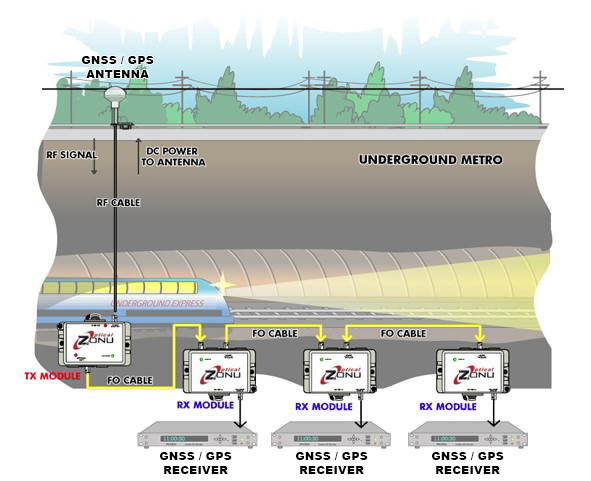
GNSS / GPS POINT-TO-MULTIPOINT (Daisy-Chain Type) FIBER LINK
- Features
- Options
- Ordering Info
- Rugged Dust-Tight Packaging
- Approx Size: 3 x 5 x 1.25 in
- Weight: 3/4 lb
- 30 MHz to 3.0 GHz Bandwidth
- High Spurious Free Dynamic Range (SFDR)
- -40C to +75C Operating Temperature
- Automatic Optical Power Control
- Manual Gain Adjust (MGA)
- Built-in Bias T for powering antenna LNA
- Built-in Low Noise Amplifier (LNA)
- CWDM Wavelength Lasers
- Internal WDM for single fiber functionality
- Extended Bandwidth 10 KHz to 3.3 GHz
- Multimode Fiber Compatibility
- Wide DC Input Range of +18 V to +30 V Supply
- Part No. A13-GPS-D31-AS-SLB GPS Fiber Optic Transmitter
- Part No. A23-GPS-00-AS-S GPS Fiber Optic Receiver
- Part No. ZA1-1-12-15-D AC to DC External Power Supply
This type of link is used for sending GNSS / GPS signals from a single source to multiple receivers which are connected sequentially. Common examples of such applications include subway, underground mine and other long tunnels. Fiber optic transmitter and receivers are packaged in semi-ruggedized, dust-tight, cast metal housings. An optional outdoor housing is available upon request. The transmitter has a built-in LNA with Lasers featuring low Relative intensity Noise (RIN) and low loss broadband matching, in order to optimize the Link performance. The transmitter also has an optional Bias-T to provide electrical power to the GPS Antenna. Specifications for this must be provided to the Factory, so OZC Support Engineering may determine a customized solution and the correct configuration.
Receivers have built-in optical splitters which are optimized to tolerate the minimum amount of signal loss.
The maximum RF input signal into the transmitter is +10 dBm and the RF interface is via a 50 Ohm SMA connector. The standard optical connector is SC/APC (FC/APC is also available upon request) for low back reflection applications. Each unit is powered through its DB-9 port and a power supply of +12 V DC is required to operate it safely. Optional alarm and monitoring functions are all also available through a DB-9 connector. A Manual Gain Control, via a potentiometer accessible from the top of the box by a small screw driver (or “tweaker”), to ease field integrations, is also available.
Note: Please contact factory for additional options such as built-in Bias T, multi-fiber compatibility, and different installation configuration involving multiple receivers.
GNSS / GPS over Fiber FAQ
What is GPS/GNSS over fiber? Distributing the signals of the location signals from satellite enable longer distance from the antenna. On locations where timing signal is required, e.g. BaseStation, Server Farms, that are either underground or far away from antenna location with sky view the RF signals received from multiple satellites are transported over fiber (RF over Fiber = RFoF). Modern system enable full redundancy, multiple antennas for backup and alternative fiber routes for security.
How does GPS/GNSS over fiber work? The RF signals received from the antennas are converted into optical signal emitted form a laser – transported over single mode or multi-mode fiber – and converter back to RF signal via a Photodetector (PD) that has the proper bandwidth to accommodate signal transport without disruption of the signal to noise ratio.
What are the advantages of GPS/GNSS over fiber? Utilizing RFoF of GPS over fiber (also GNSS over Fiber) enable longer distance from the antenna to the equipment, redundancy, resilience from EMI interference, and multipoint distribution via optical splitting AND RF splitting at the receiver.
Why use fiber instead of coax for GPS/GNSS timing? Coax attenuation impact signal to noise ratio for distances over 10m. GNSS signals are at the approximate frequency of 1.6 GHz – coax distribution is not practical due to the excess attenuation.
Can GPS/GNSS over fiber support long-distance antenna installations? RFoF enable seamless signal transport and splits of kilometers range – basically enable any distance from the antenna to the edge equipment.