
Optical Zonu fiberoptic delay lines incorporate wideband lasers and photodiodes (fiberoptic transmitters and receivers) designed for linear analog modulation. Fiberoptics provide high bandwidth and sensitivity to facilitate long delays, and wide spur free dynamic range for operation over a variety of loss budgets. The basic advantage of a fiberoptic delay line is that long lengths of optical fiber are extremely low loss, broadband, and can be coiled into small packages. Delays up to 80 microseconds, phase linearity better than 0.01%, and RF bandwidths to 40+ GHz can be achieved in the form factor shown below. Delays up to 2200 microseconds can be accommodated in rack mounted systems. The RF input and output interface is via 50 Ohm SMA connectors. Optional extended operating temperature range of -20C to +85C is available.
Basic fiberoptic delay line applications include the following:
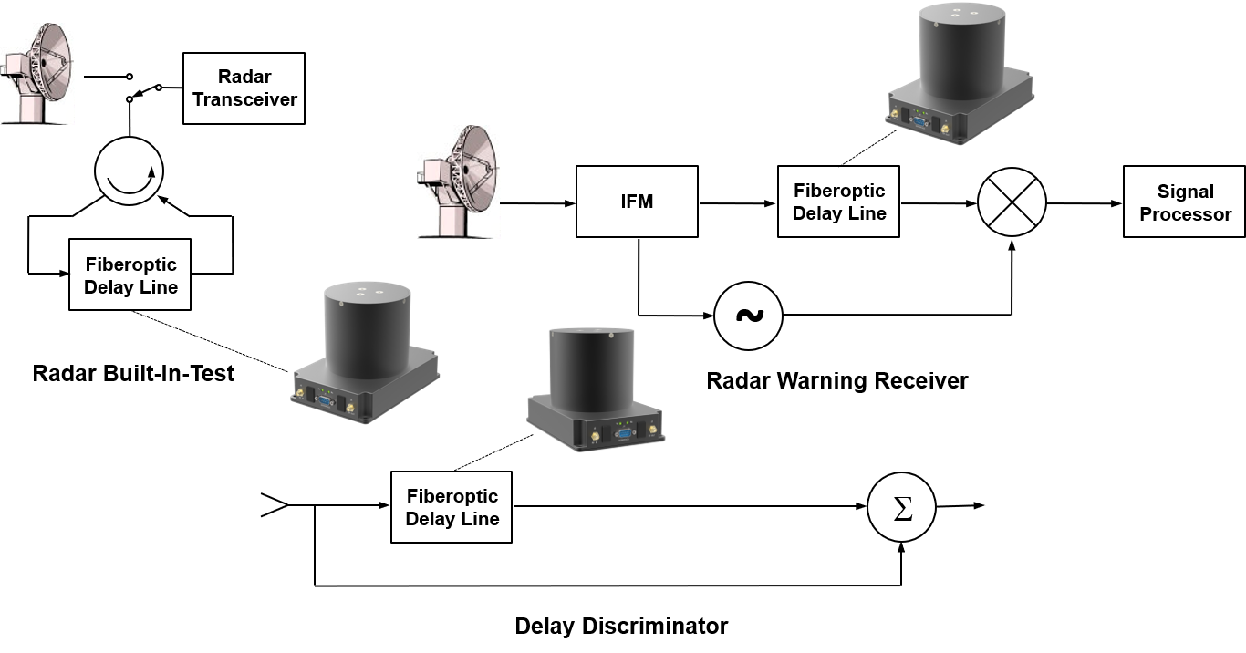
Radar Systems BIT (built-in-test) – Fiberoptic delay lines are used as BIT equipment for radar systems. Radar systems generally have some dead time between last echo received and next transmitted pulse. Some self testing is accomplished during this time (noise performance, dc tests, etc.). In addition, the system may periodically break its operational cycle to perform self testing with a simulated echo. The same kind of testing is also performed during manufacturing and as part of regular ground-based system testing.
Antenna Systems Variable Delays – Varying delays at multiple antennas may be used to store and time multiplex signals from a number of antennas for processing at a single receiver.
Synthetic Aperture & Phased Arrays – Varying delays may also be used to direct multi-antenna beam patterns in synthetic aperture or phased array applications.
Moving Target Indication and Clutter Cancellation – Each received echo pulse is subtracted from the previous echo, which has been stored in the delay line. Any component of the signal that has not changed will be subtracted from itself to give a zero output. This could be ground clutter or a stationary target. A moving target will generally have an amplitude change as well as a Doppler frequency shift. The difference between successive pulses in this case will result in a dc or low frequency output proportional to the frequency (phase) shift (speed information) and the change in amplitude.