
eT - High Capacity D2D RF Transport
Home » Solutions » Satellite Communication » eT – High Capacity D2D RF Transport
- Features
- Options
- Applications
- Up to 10 Broadband Signals (Polarities) / LPN / TTL (each unidirectional)
- 30 MHz to 6 GHz RF Over Fiber (3 GHz and 4 GHz Bandwidth Options Available)
- Field replaceable optical modules
- -20°C to +60°C Outdoor Unit Operating Temperature Range
- IP-65 Rated Outdoor Unit
- 19” 1RU Rack Mounted Indoor Unit
- CWDM Wavelengths Facilitate Single Fiber Transport Between ODU and IDU
- Remotely Controlled Gain to Optimize Gain, Noise Figure, IIP3 for Mission Link Margin
- High SFDR for High-Fidelity Analog Transport
- Low Phase Noise Reference Clock Distribution
- Local LEDs and Dry Contact Alarms (Indoor Unit)
- Remote Control/Monitoring up to full NMS Integration
- Lasers Conform to Class 1 Emission Level Per CDRH and IEC-825 (EN 60825) Standards
- Redundant Auto-Switching Fiber Between ODU and IDU for Increased Releiability
- Integrated +20 dB (or +40 dB) Transmitter LNA for Low Received-Power Downlinks
- RF Power Monitors for Reporting and Closed Loop Gain Control (AGC)
- Extended High Frequency – 4. 0 or 6.0 GHz
- Extended Low Frequency -down to 10 kHz
- Ethernet connectivity – GbE (local switch for network connection)
- -48VDV supply option (AC for special projects)
- Various Architectures for Reference Clock Distribution to LNBs and BUCs
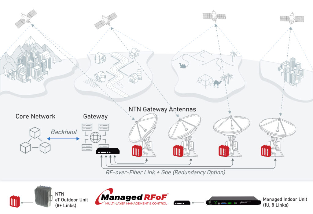
- Antenna to Core Connectivity Over Fiber for Non-Terrestrial Networks (NTN)
- High-Capacity Ground Segment D2D (Direct-to-Device) Feeder Links
- Wideband Signal Transport Across Wireless, Satellite, and Phased-Array Systems
- Ultra-Low-Latency Links with Multi-Octave Bandwidth for Time-Sensitive RF Paths
- 3GPP Compliant Antenna Remoting Over Fiber (Architecture Dependent)
- Polarization, Frequency, Antenna, and Site Diversity Architectures for Resilient Ground Segments
- RF Over Fiber Transport
- Teleport RF Signal Distribution and Antenna Remoting
- RF Over Fiber Transport Where Coaxial Cable is Impractical or Additional Security is Required
- Oil & Gas Platforms
- TVRO – VSAT
Description
In Non-Terrestrial Network (NTN) architectures, high bandwidth is critical for transforming satellites from simple “relays” into robust extensions of 5G and 6G ecosystems. It enables the network to handle data-intensive applications in regions where traditional terrestrial infrastructure is absent. High bandwidth allows NTNs to move beyond simple text-based emergency messaging to support broadband-heavy services in remote areas and at distributed gateway sites.
The eT family of high-capacity broadband fiber links connect satellite antennas and ground segments (gateways) to the terrestrial core telecommunications network, facilitating connectivity to standard user devices. A single eT transport link can accommodate any combination of up to ten uplinks and/or downlinks. These links support transport of data, voice, or IoT information from LEO (Low Earth Orbit) satellites to the core network via feeder link infrastructure.
The eT L/S/C-Band SATCOM fiber transport subsystem provides a dense, cost-effective, and reliable RF connection between a satellite antenna and a SATCOM modem in those cases where coaxial cable is impractical or additional security is required. Fiber optic transmitters feature linear uncooled isolated DFB laser diodes. Fiber optic receivers feature high performance InGaAs photodiodes. The standard transported RF frequency band with high spur free dynamic range (SFDR) is 30–3000 MHz. Options exist for extending the frequency range to 6 GHz on the upper end, and/or 10 kHz on the lower end.
The eT fiber subsystem utilizes Coarse Wavelength Division Multiplexing (CWDM) to transport all RF signals between the Indoor Unit (IDU) and the Outdoor Unit (ODU) over a single fiber. Low phase noise reference clocks may be transported from SATCOM modems or timing servers to elements at the antenna in a number of ways. An optional low noise transmitter pre-amplifier ensures a margin on signal-to-noise ratio (especially on low received power downlinks) while keeping the signal in the most linear operating range of the fiber link. Diversity support for multiple fiber routes is optional.
The eT transport subsystem may be monitored in a number of ways. Locally, LEDs and dry contact relay alarms (IDU) provide status. There are multiple ways to monitor the subsystem remotely including SSH command line interface (CLI), HTTP web user interface, and Optical Zonu’s Managed RFoF graphical command and control interface. The management interface also supports SNMP v2 and v3 and the RESTful API.
The standard RF interface is 50Ω SMA (IDU) and 50Ω N (ODU). The ODU is powered from 12 VDC (-48V optional). The IDU may be powered from AC or 48 VDC.
FAQ
For Satellite Communication Feeder line (RFoF)
What is RF over Fiber (RFoF)? And why 6 GHz is critical?
6 GHz RF over Fiber (RFoF) is a signal transport architecture that carries analog radio frequency signals over fiber optic cable rather than traditional coaxial cable. Instead of converting the signal into digital data packets, RFoF preserves the original analog waveform and transports it optically between the antenna and indoor equipment. This approach combines the performance advantages of fiber optics with the simplicity of analog RF transport. The 6GHz enables very high instantaneous bandwidth that current digital system can’t duplicate.
How does RFoF work?
In an RFoF system, the analog RF signal is connected directly to an optical transmitter located near the antenna. A high-linearity laser converts the electrical RF signal into corresponding variations in light intensity. The optical signal then travels over single-mode fiber to the receiving equipment, where a photodiode converts the light back into an identical analog RF signal. Because the process is transparent to the communications protocol, the original signal characteristics are preserved throughout the transport path, allowing it to accommodate spread-spectrum and other advanced modulation techniques to remain future-proof.
Where is 6 GHz RFoF commonly used?
6 GHz RFoF is widely used in satellite ground stations, teleports, gateway facilities, defense communications networks, and telecommunications infrastructure. It is valuable in applications where long-distance signal transport, wide bandwidth support, low latency, and high signal fidelity are critical requirements. It is currently in wide deployment of commercial services worldwide.
Why is fiber optic cable used instead of coaxial cable?
Fiber optic cable offers significantly lower signal loss over long distances than coaxial cable. This allows operators to place antennas much farther from indoor equipment without degrading signal quality. Fiber is also immune to electromagnetic interference, helping protect sensitive satellite and telecommunications signals from external noise sources. You can imagine the benefits this has in any mission critical situation whether commercial or military.
Why is the architecture designed for up to 6 GHz?
The 6 GHz range is a great balance between performance, flexibility, and commercial deployment requirements. Operators can transport much wider bandwidths than traditional L-Band intermediate frequency systems while supporting a broad range of satellite and telecommunications applications. The frequency range also aligns well with C-Band operations, allowing native RF signals to be transported directly over fiber without requiring additional frequency conversion at the antenna.
How does 6 GHz RFoF improve on traditional L-Band architectures?
Traditional satellite ground systems often rely on L-Band intermediate frequencies to minimize signal loss in coaxial cable. With RFoF, the low-loss characteristics of fiber remove many of these constraints. Operators can transport wider sections of spectrum at higher intermediate frequencies, providing greater flexibility for modern high-capacity satellite services while reducing the limitations associated with crowded L-Band infrastructure.
How does RFoF compare with Digital Intermediate Frequency (IF) architectures?
RFoF and Digital IF architectures address similar transport requirements but use different approaches. RFoF maintains the signal in its original analog form, while Digital IF systems convert the RF signal into digital data for transport over IP networks. RFoF is valued for its simplicity, low latency, and ability to handle wide bandwidths without requiring high-speed analog-to-digital conversion. On the other hand, Digital IF systems often provide greater flexibility for routing and distributing signals across standard network infrastructure.
What are the performance advantages of RFoF?
Because RFoF transports the signal as an analog waveform, it avoids the need for high-speed analog-to-digital converters at the antenna. It provides higher instantaneous bandwidth with higher dynamic range while eliminating quantization noise and minimizing processing latency. RFoF systems can also support very wide instantaneous bandwidths, making them well suited for demanding satellite communications and telecommunications applications. However, using RFoF effectively requires specialized design that is not currently produced for mass markets and should not be treated as a commodity purchase.